
IGBT Module Selection Parameters: A Technical Guide to Voltage, Current, and Switching Ratings
Direct answer: IGBT module selection is a constraint-matching exercise. The voltage class must cover the DC-link and transient overvoltage; the current rating must cover continuous and peak overload current with the cooling system actually used; the switching rating must match the converter frequency and acceptable switching loss; and the thermal path must be able to move heat from the silicon chip through the ceramic substrate and copper baseplate into the heatsink. A module that looks strong on one headline number can be the wrong choice once these four parameters are read together.
This guide is written for design engineers who read datasheets before committing to a design. It uses verified product facts from Jiangsu core diamond times Electronic Technology Co., Ltd., a Kunshan-based supplier of power electronic components including IGBT modules, fuses, power semiconductors, semiconductor modules, diodes, and thyristors. The company was established in 2022, serves the EU, USA, Australia, and Middle East markets, and exports about 50% of its sales.
Problem Definition: Why Headline Parameters Mislead
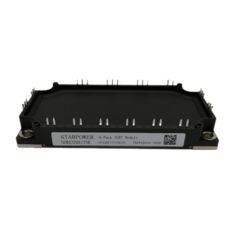
The usual selection error is to compare only the nominal current or the voltage number. That approach hides the parameters that decide whether the module survives in service. An IGBT module is a power semiconductor module that contains IGBT chips and freewheeling diodes; its datasheet describes electrical limits, switching behavior, thermal resistance, isolation, and package constraints. The design question is not “which module has the largest number?” but “which module keeps junction temperature, overvoltage, and short-circuit stress inside the allowed range for this topology?”
Four trade-offs dominate the decision:
- Voltage class versus conduction loss. A higher voltage class usually gives more overvoltage margin, but the device may have higher conduction and switching losses. The rated voltage must be read against the actual DC bus and the overvoltage spike produced by the layout and switching speed.
- Current rating versus thermal path. The current printed on the datasheet is not a free-standing guarantee. It depends on case temperature, cooling, switching frequency, and the allowed junction temperature. The same module can carry more current in a well-cooled stack than in a compact cabinet with poor airflow.
- Switching frequency versus loss. During turn-on and turn-off, voltage and current overlap for a short period. The power lost in that overlap is switching loss, and it increases with higher switching frequency. Higher frequency can shrink magnetics and filters, but it also pushes more heat through the thermal path.
- Package versus drive and topology. Single-switch, dual-switch, and full-bridge packages serve different circuits. The package must fit the drive board, the heatsink, the isolation distance, and the maintenance plan.
Selection principle: Read the datasheet as a system map. Voltage class sets the overvoltage ceiling. Current rating sets the conduction window. Switching ratings set the frequency penalty. Thermal data sets the real continuous capability. Protection and package data set whether the design can be built and serviced.
Industry Background: Where IGBT Modules Sit
IGBT modules are a central component in inverters for electric drives, battery chargers, solar systems, and wind power applications. In the supplier portfolio described in this guide, IGBT modules are intended for power inverter, UPS, welding machine, new energy power conversion, and motor drive scenarios, and for the new energy, power supply, industrial automation, welding equipment, electric motor drive, and UPS industries. That application range explains why one parameter set cannot fit every design: a welding machine, a solar inverter, and a UPS do not see the same load profile or cooling environment.
The market context also matters for technology choice. The global IGBT market was estimated at USD 9,202.9 million in 2024, with a projected CAGR of 11.02% from 2025 to 2035. The global SiC module market was estimated at USD 980.7 million in 2025. SiC modules are an alternative for high-frequency and high-efficiency designs, but IGBT modules remain a broad base for industrial power conversion. For a design engineer, the practical conclusion is not to switch technology by default, but to confirm whether the voltage, current, switching, and thermal targets are better met by an IGBT module or by another power semiconductor module.
Detailed Solution: Reading the Four Core Parameters
1. Voltage Class: Match the Ceiling, Not the Label
Start with the maximum voltage the module will see, including the DC-link voltage and the overvoltage spike generated when current is interrupted. The IGBT module range in the verified product facts covers a voltage rating of 600 V to 1700 V. That range is the shortlist boundary, not an automatic choice. A 1200 V class and a 1700 V class can both be “available”; the correct one is the lowest class that still leaves enough margin for the actual overvoltage stress and the specified reliability target.
Voltage class also interacts with the freewheeling diode and the rectifier stage. The verified fast recovery power diode family has a peak repetitive reverse voltage of up to 2800 V, with a forward current range of 100 A to 1800 A. Those figures belong to the fast recovery power diode row, not to the IGBT module row. The distinction matters in a rectifier or power-supply topology: the IGBT may switch the primary or the inverter leg, while the rectifier diode blocks a different reverse voltage. Confirm each device against its own duty.
2. Current Rating: Continuous, Overload, and Cooling
The verified IGBT module range covers a current rating of 50 A to 1200 A. The datasheet current is only meaningful with its test conditions. For selection, build a current profile with three levels: normal continuous current, short-time overload current, and fault current. The rated current should be reserved with sufficient margin according to the continuous working current and peak overload current of the system. A module selected only for the continuous value may fail during motor starting, welding pulses, or battery-charger surge.
Current rating is also tied to the freewheeling diode. In the fast recovery power diode family, the forward current range is 100 A to 1800 A. If the topology uses a separate rectifier or freewheeling path, compare the diode current waveform with the IGBT current waveform. Do not transfer the IGBT current rating to the diode or the reverse. Each device has its own thermal and surge limits.
3. Switching Frequency: The Loss Multiplier
Switching loss is generated during the turn-on and turn-off transition, when voltage and current overlap. It increases with higher switching frequency. The verified IGBT module facts include low saturation voltage and high switching speed. Those two properties are useful, but they must be read together: a low saturation voltage reduces conduction loss, while high switching speed can reduce switching loss per event. The design still has to calculate total loss at the intended frequency and cooling condition.
For a motor drive or solar inverter, the switching frequency may be chosen to reduce current ripple, acoustic noise, or filter size. For a welding power supply or a high-frequency charger, the frequency may be much higher. In both cases, the thermal path must carry the sum of conduction loss and switching loss. If the thermal margin is thin, reducing frequency or selecting a module with lower switching loss is more effective than increasing the current rating alone.
4. Thermal Path: From Silicon to Heatsink
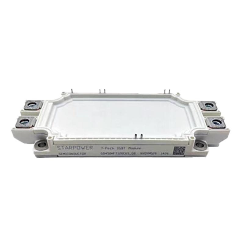
IGBT module construction in the verified facts uses an aluminum ceramic substrate, copper base plate, silicon chip, and plastic housing. The fast recovery power diode uses a silicon wafer, copper base, and ceramic housing. These material stacks are not cosmetic. They define the thermal path from the semiconductor to the baseplate and then to the heatsink. A good electrical selection can still fail if the thermal stack is poor.
Common overheating causes include insufficient heat dissipation, uneven thermal grease, loose mounting screws, an operating current above the module rating, a blocked radiator, and an abnormal gate drive signal that creates extra loss. The installation check should confirm fan or cooling-water capacity, thermal grease coating and baseplate flatness, actual working current and overload condition, and screw tightening torque. The goal is not only to install the module, but to reproduce the thermal resistance assumed in the selection calculation.
Thermal warning: Do not use the datasheet current as a stand-alone purchasing number. Confirm the cooling method, the thermal interface, the mounting torque, and the ambient temperature of the cabinet. If any of these change, the usable current changes with them.
5. Short-Circuit Withstand and Protection
IGBT short-circuit withstand time is the maximum time that an IGBT can sustain short-circuit current under specified test conditions before device failure. A longer withstand time gives a higher safety margin for the power system, but it does not replace a fast gate drive and a correctly selected fuse. The protection chain must detect the fault, turn off the IGBT, and limit energy before the module is damaged.
The verified industrial power fuse range covers a rated voltage of 690 V to 1500 V and a rated current of 10 A to 1250 A, with high breaking capacity and a time-delay characteristic. It is designed for short-circuit and overload protection in industrial power, energy storage, and power conversion systems. Fuse selection is a separate exercise from IGBT selection, but the two must be coordinated. A fuse that is too slow may let the IGBT absorb too much fault energy; a fuse that is too fast may nuisance-trip on normal surges.
6. Package, Topology, and Drive Compatibility
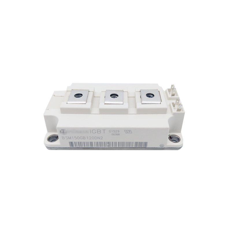
The verified IGBT module facts describe a single/dual IGBT chip structure and an isolated baseplate. Package selection should follow the circuit: a high-current power converter may use a full-bridge or half-bridge module package; a compact cabinet may need a small-size module with high power density; a high-vibration environment may need a package with high mechanical stability. The heat sink structure, mounting space, pin definition, and drive-board compatibility must be checked before the design is released.
Part-number families can encode switch configuration. For example, Infineon’s published IGBT module part-number designator uses FF for dual switch, FZ for single switch, FS for 3-phase full bridge, and FP for power integrated. That naming convention is specific to Infineon, but the lesson is general: read the package code and the circuit symbol together, not the current rating alone.
7. Freewheeling Diode and Reverse Recovery
The freewheeling diode inside an IGBT module provides a path for inductive current during IGBT turn-off and suppresses voltage spikes to protect the chip. In rectifier and power-converter stages, reverse recovery behavior affects switching loss and EMI. The verified fast recovery power diode family is described as having low forward voltage drop, fast reverse recovery, and high surge current capacity, and is intended for rectifier, welding machine, and power converter applications. If the topology separates the rectifier from the IGBT, confirm the diode’s reverse recovery and surge rating against the actual commutation loop.
Step-by-Step Breakdown: A Parameter Confirmation Workflow
- Define the electrical envelope. Record the DC-link voltage, output current, overload profile, switching frequency, ambient temperature, cooling method, and target service life. These inputs decide which datasheet columns are relevant.
- Shortlist the voltage class. Use the IGBT module voltage range of 600 V to 1700 V as the available field. Select the lowest class that covers the DC-link and the allowed overvoltage spike. For rectifier diodes, check the peak repetitive reverse voltage separately; the verified fast recovery diode range goes up to 2800 V.
- Build the current profile. Separate continuous current, peak overload current, and fault current. Compare them with the IGBT current range of 50 A to 1200 A and the diode forward current range of 100 A to 1800 A. Apply margin to the continuous and peak values, not only to the nominal value.
- Estimate conduction and switching loss. Use the datasheet saturation voltage and switching energy at the actual current, voltage, and gate resistance. Remember that switching loss rises with frequency. If the loss budget is tight, revisit frequency, gate drive, or module selection.
- Check the thermal path. Confirm the aluminum ceramic substrate and copper base plate are mounted with the specified thermal grease, flatness, and torque. Verify that the heatsink can remove the total loss at the cabinet ambient. Do not accept a thermal calculation that assumes a cooling condition the cabinet cannot deliver.
- Verify short-circuit protection. Confirm the gate drive can detect and clear a short circuit within the module’s withstand time. Coordinate the industrial fuse rating and time-current characteristic with the IGBT and the load.
- Confirm package and drive compatibility. Check single/dual/full-bridge configuration, isolated baseplate, pin definition, creepage distance, mounting space, and drive-board interface. A mechanically correct module can still be electrically incompatible.
- Validate the sample and the handling plan. Before production, test the sample in the real stack. Store unused modules in original anti-static packaging at -10°C to +40°C and relative humidity ≤70%, away from dust, corrosive gas, and static fields. Do not stack heavy goods on the modules.
Use Cases: How the Same Parameters Shift by Topology
Solar inverter and motor drive
These applications usually run continuous power conversion with a defined overload profile. The IGBT module is selected for the inverter leg, and the freewheeling diode carries reactive current. The key checks are voltage class against the DC bus, current rating against the maximum motor or inverter current, switching frequency against the loss budget, and thermal path against the cabinet cooling. The verified application scope includes solar inverter, motor drive, and new energy power conversion.
UPS and industrial power supply
A UPS or industrial power supply may operate at high switching frequency and may have a compact cabinet. The thermal path is often the limiting factor because the cabinet volume is small. The verified IGBT module range includes UPS and power supply applications, and the verified bridge rectifier module range covers AC-DC power conversion with a peak reverse voltage of 800 V to 2000 V and an average forward current of 25 A to 800 A. In these designs, the rectifier stage and the inverter stage should be checked as separate thermal zones.
Welding equipment and power converter
Welding power supplies and power converters often have pulse loads and high surge current. The current rating must be read with the overload profile, not only the average current. The verified fast recovery power diode family is intended for welding machine and power converter scenarios and has a forward current range of 100 A to 1800 A and a peak repetitive reverse voltage of up to 2800 V. The thyristor range is also relevant for rectifier and welding power supply control, with a voltage rating up to 3000 V and a current rating of 1100 A.
Comparison Table: Verified Power Device Ranges and Design Roles
| Device | Verified parameter range | Typical role in the circuit | What to confirm first |
|---|---|---|---|
| IGBT module | Voltage rating 600 V to 1700 V; current rating 50 A to 1200 A; single/dual IGBT chip structure; isolated baseplate; low saturation voltage; high switching speed. | Power inverter, UPS, welding machine, new energy power conversion, motor drive. | Voltage class against DC-link and overvoltage; current margin against overload; switching loss at the intended frequency; thermal path. |
| Fast recovery power diode | Peak repetitive reverse voltage up to 2800 V; forward current 100 A to 1800 A; low forward voltage drop; fast reverse recovery; high surge current capacity. | Rectifier, welding machine, power converter. | Reverse voltage and reverse recovery; surge current; thermal coupling with the IGBT. |
| MOSFET module | Drain-source voltage 60 V to 1200 V; drain current 30 A to 300 A; low on-resistance; high switching frequency; isolated baseplate. | High-frequency inverter, charger, switching power supply. | On-resistance and switching loss at high frequency; package thermal path. |
| Thyristor / SCR | Voltage rating up to 3000 V; current rating 1100 A; high surge current capability; low on-state voltage. | Rectifier, soft starter, welding power supply, industrial power control. | Surge current; gate drive; cooling; coordination with fuses. |
| Bridge rectifier module | Peak reverse voltage 800 V to 2000 V; average forward current 25 A to 800 A; low forward voltage drop; isolated baseplate. | AC-DC power conversion, power supply, welding machine, motor control. | Average current and reverse voltage; isolation; heatsink mounting. |
The 2800 V and 1800 A figures in this table belong to the fast recovery power diode row. The IGBT module row uses the verified IGBT range of 600 V to 1700 V and 50 A to 1200 A.
FAQ: Parameter Confirmation and Sourcing Checks
What are the storage requirements for unused IGBT modules?
Store unused IGBT modules in their original anti-static packaging. The environment should be -10°C to +40°C with relative humidity ≤70%. Avoid dust, corrosive gas, and static fields, and do not stack heavy goods on the modules.
What voltage class and current rating should be confirmed first?
Confirm the IGBT voltage class against the maximum DC-link voltage and the overvoltage spike allowed by the layout; the verified IGBT module range is 600 V to 1700 V. Then confirm current against continuous and peak overload current; the verified IGBT current range is 50 A to 1200 A. For a rectifier diode path, confirm the peak repetitive reverse voltage separately; the verified fast recovery power diode range goes up to 2800 V with a forward current range of 100 A to 1800 A.
How should switching frequency and thermal path be compared?
Switching loss is generated when voltage and current overlap during turn-on and turn-off, and it increases with higher switching frequency. Compare the datasheet switching energy at the actual voltage, current, and gate resistance, then verify that the thermal path can remove the total loss. The verified IGBT module construction uses an aluminum ceramic substrate, copper base plate, silicon chip, and plastic housing. Confirm thermal grease, baseplate flatness, heatsink capacity, and screw torque, because uneven grease, loose screws, a blocked radiator, or excessive current can cause overheating.
What are common symptoms of IGBT module turn-on failure?
An IGBT module that fails to turn on may show no output power. Verified causes include a missing gate drive power supply, an open or poorly contacted gate wire, internal IGBT chip damage, wrong gate signal logic, and an interlock protection that has activated and locked. For an overheating alarm, check thermal grease, screw torque, actual working current, radiator blockage, and gate drive waveform.
Can I request a sample and technical support for parameter confirmation?
Jiangsu core diamond times Electronic Technology Co., Ltd. supplies IGBT modules and fuses, supports small trial orders and bulk volume orders, and maintains a technical team of five support engineers for component selection and working-condition review. Products are inspected before shipment. To request a sample, confirm a parameter set, or discuss a project, contact xinzuanshidai@163.com, +86 13675967789, or WhatsApp +86 13675967789. The company is ISO9001:2015 certified (June 2026).
Conclusion: A Parameter Set, Not a Single Number
IGBT module selection is settled by the combination of voltage class, current rating, switching behavior, and thermal path. The verified product facts give a practical starting field: IGBT modules from 600 V to 1700 V and 50 A to 1200 A, fast recovery power diodes up to 2800 V and 100 A to 1800 A, and companion thyristors, MOSFETs, bridge rectifiers, and fuses for the rest of the power stage. The design engineer still has to confirm the actual DC-link stress, overload profile, switching frequency, cooling condition, short-circuit protection, package compatibility, and storage plan.
Use the checklist in this guide before releasing a design: shortlist the voltage class, build the current profile, estimate switching loss, verify the thermal stack, coordinate protection, confirm the package, and validate a sample. That sequence turns a datasheet comparison into a defensible selection decision.
Next step: confirm the parameters against your circuit
If you are comparing IGBT modules for an inverter, rectifier, power supply, UPS, welding machine, or motor-drive project, prepare the DC-link voltage, continuous and overload current, switching frequency, cooling method, and package constraints. Jiangsu core diamond times Electronic Technology Co., Ltd. can support component selection, small trial orders, and bulk orders. Visit www.xinzuanshidai.com or download the product catalog.

Have Questions or Need More Details?
Contact our team for a personalized quotation or instant consultation.
Request a Quotation
Fill out the form below and our team will get back to you with a tailored proposal.
WhatsApp Direct Chat
Prefer to chat in real-time? Message us on WhatsApp for instant assistance & quick answers.
- Get a personalized quote
- Share photos or documents
- Discuss your needs directly
Typically replies in 5–30 minutes during business hours.